As an exploration into the potential performance of a very simple amplifier, the Zen amplifier has succeeded in creating notoriety and some controversy over the last 8 years. More importantly, it's novel and simple construction appears to have encouraged a large number of doit- yourselfers to take up a soldering iron and jump in.
Having only a single gain device, the design's name is a pun on the Zen Koan, "What is the sound of one hand clapping?", but the point is quite serious. High quality sound can be obtained with simple and accessible circuits. Conversely, it is quite easy to design a complex circuit which sounds subjectively lifeless or even irritating.
This is Part 1 of the Zen Variations, and each part will illustrate one of the many ways to build a single stage audio amplifier. There are a lot of possibilities here; I recently counted out several hundred permutations. After considerable meditation, I winnowed these down to approximately 30 interesting and non-trivial examples, and it is these we will explore one at a time in no particular order.
The Original Zen Amps
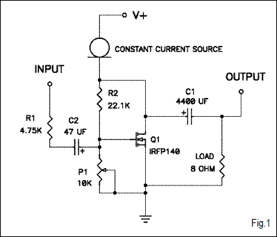
Figure 1 is the simplified schematic of the original Zen Amp. Here we see a single gain device, a power MOSFET, operated in Common Source mode, where the input comes into the Gate of the device and the output which drives the loudspeaker comes out of the Drain. The MOSFET is biased by a constant current source from the positive supply, and a small network of resistors and capacitor set up the operating voltages and provide feedback. The full article can be found
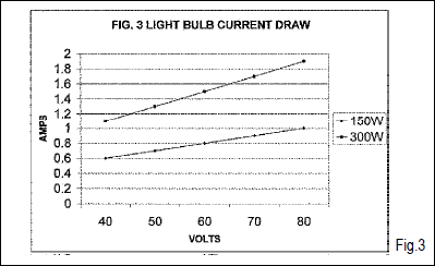
I went out and bought all sorts of samples of light bulbs. A little measurement revealed that common household incandescent bulbs are quite useful for our purpose. Figure 3 shows the current versus voltage for a couple of 120 Volt lamps, one rated at 150 watts, and the other at 300 watts. The resistance (in ohms) of each of these at any point is simply the volts divided by the amps.
* ( Personally, I don't care for cute section titles, but if I don't put them in, somebody at Audio Express does. )
Schematic Lite
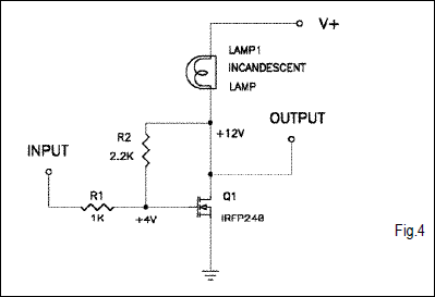
Figure 4 shows the simplified schematic of a Zen Amp using a light bulb instead of a constant current source. The input goes into the Gate and comes out the Drain. The two resistors R1 and R2 set up the bias voltage for the Gate, which has to operate at approximately 4 volts above the Source, which is grounded. The two resistors also provide feedback for gain control and distortion reduction.
The Drain voltage of this circuit is the operating Gate voltage (Vgs) times (R1+R2)/R1. In this case with R2 = 2 x R1, and Vgs of 4 volts, the Drain voltage is set at 12 Volts DC. This ratio of 2:1 of resistance also sets the gain of the circuit which is approximately R2/R1, or 2X, which is 6 dB.
This is a perfectly workable circuit with a 200 or 300 watt light bulb and a clean 40 to 80 Volt supply. It has a couple of small limitations: it
L1. For L1 I used either MCM #50-1080 (www.mcmelectronics.com) or the ERSE 4.0 mH / 14 Gauge (www.zalytron.com). I tested both up to 6 amps DC current without seeing loss of inductance, and I believe the ERSE will do more.
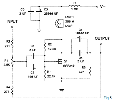
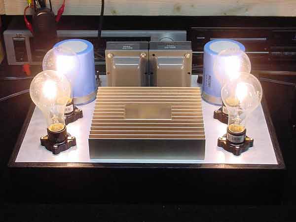
Figure 5 shows the use of a 300 watt Sylvania bulb. We will later be showing performance of 2 such bulbs in parallel for more bias current. Depending on the supply voltage and the dissipation capability of the heat sinks, more bulbs can be placed in parallel to get the desired bias current. Can't find a 300 watt bulb? Two 150 watt bulbs in parallel behave virtually the same, and two 200 watt bulbs are perfectly workable for a little more bias current.
The light bulbs were set in standard Leviton sockets found at the local hardware store. The clear 300 watt bulbs came from the McMaster-Carr catalog (www.mcmaster.com). I believe you can get the sockets there also.
I have specified the IRFP240 MOSFET transistor in Figure 5, but a wide range of similar N channel devices will work fine. The best performance is obtained with the IRFP040 or IRFP044, but unfortunately they seem very difficult to get. An in-between alternative is the IRFP140. When substituting other MOSFETs, the Gate to Source pin operating voltage becomes an important consideration. We will want a Drain voltage of about 12 to 15 volts, and if the Vgs of the MOSFET chosen is very different from about 4 volts, you will need to adjust the value of R1. Decreasing R1 will raise the Drain voltage, and of course increasing R1 will lower the Drain voltage.
MOSFETs are sensitive to damage with high Gate voltages, most specifically static electricity. Always take modest care to avoid static discharge when handling the parts. Personally, I take almost no precautions, and I hardly ever have a problem, so don't get too worried about it, particularly once the transistor is wired into the circuit.
Unlike some previous projects with MOSFETs, there are no zener protection diodes on the input of the amplifier. This again means that some modest care should be use when attaching an input cable, but this simply means touching the ground connections first. If both the source and amp are earth grounded via the wall outlet, you don't even have to think about it.
You may ask, is there a PC board layout for this project? No. The small quantity and odd nature of the parts lends itself better to point-to-point
proper signal polarity, the speaker + terminal goes to ground.
Even More Incandescence
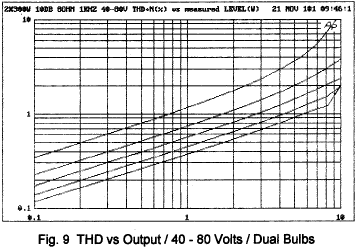
It is practical to increase the current through the MOSFET, and improve the performance, by paralleling lamps. Figure 9 shows the harmonic distortion of the circuit of Figure 5 with twin 300 watt lamps in parallel. The distortion drops substantially and there is more power.
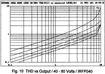
Figure 10 shows a further improvement available with a different MOSFET, the hard to find IRFP040, where the distortion is seen to drop by about 1/3.
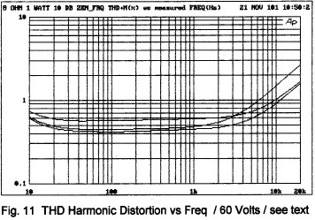
Figure 11 documents three distortion versus frequency curves for the
The lower voltage chips of the same type will give lower distortion, apparently due to their lesser sensitivity to voltage fluctuations on the Drain. They are generally the preferred parts.
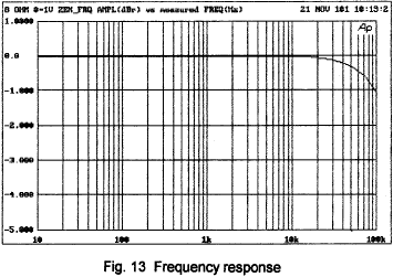
For some unknown reason, the Zen amplifiers have been criticized as having low bandwidth, but I have not seen a case where this has been true. Fig 13 documents the frequency response of this Zen amp, showing -1 dB at 100 KHz.
The damping factor of the Zen amp is quite low, reflecting the paucity of negative feedback in the design. With the IRFP240 devices, the damping factor was about 8 referenced to 8 ohms, and about 12 with the IRFP040's.
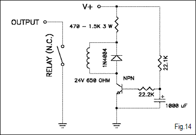
The circuit of Figure 5 has a substantial turn-on thump as the voltage across the MOSFET goes from 0 to 15 volts, and some of your more sensitive speakers might take offense. Figure 14 shows a simple turnon delay circuit which will short the output of the amp to ground for a few seconds. The relay in this case is #Z789-ND from Digikey with the switch contacts wired Normally Closed. The transistor is a generic NPN device rated at 1 amp and 100 volts. When the power supply is applied, the capacitor in the circuit slowly charges up until it turns on the transistor, which opens the relay switch. You will notice a resistor in series with the relay coil to adjust the voltage across the coil to its rated voltage versus the supply voltage. If you go with the 80 volt supply, this resistor will probably need to be 5 watts, but with 60 volts you can use 3 watts. Alternatively, you can simply use a switch to short the output to ground manually. Two other solutions: A lower value of output capacitor, or a power supply which turns on slowly. The circuit does not have a substantial turn-off thump, and so there is no need to address that situation.
in Audio Amateur 2/94, with a revision in 3/94. It is also available on line at www.passdiy.com .
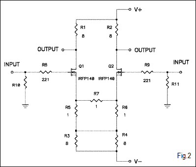
The Zen was followed up by Son of Zen (Audio Amateur 2/97) whose unsimplified circuit is seen in Figure 2. Here a single gain stage is formed by a differential pair of identical devices, allowing greater simplification and the removal of coupling capacitors and negative feedback.
Both these designs also inspired preamplifying circuits based on the same topologies, giving us Bride of Zen (Audio Amateur 4/94) and Bride of Son of Zen (Audio Electronics 5/97).
Let There Be Light *
Some of the DIYers who built the Zen Amp were put off by the complexity of having a constant current source comprised of two additional transistors and several resistors. However a constant current source can be replaced by a high power resistor in the Zen Amp, if you are willing to use a higher supply voltage and a resistor with high enough value to simulate a constant current source for practical purposes.
At the same time, others complained of the difficulty of obtaining the high power resistors required for the Son of Zen. I get a few such complaints, but they have been a source of inspiration.
And so the light came on and I had a bright idea: A light bulb is a power resistor which is conveniently obtained and which can dissipate large amounts of power without a heat sink. So what kind of light bulb might be appropriate?
requires a signal source which is direct coupled and which can sink about 4 mA, and a load which doesn't mind 12 volts of DC. These conditions can be met in quite a few cases, but are not to be counted on for most systems.
Another limitation is that the AC gain setting is the same as the DC bias point, and it is often convenient to be able to separate these two settings.
Further Schematic Illumination
Figure 5 shows a real schematic which remedies these shortcomings. The supply voltage is made quieter by inductor L1 and capacitor C3 which remove noise from whatever supply is represented by V+. C2 capacitively couples the input so that we don't have to worry about the DC characteristic of the signal source. C1 capacitively couples the output to the speaker so the woofer cone doesn't fall out onto the floor. R1 and R2 are still there, and they set the DC bias point of the MOSFET Q1. A potentiometer P1 (Digikey 381N252-ND) and two new resistors R3 and R4 set the AC gain of the amplifier, which is variable from approximately -20 to +20 dB referenced to the input voltage. The feedback loop represented by this potentiometer encloses the input and output capacitors of the amplifier and imposes correction on distortion they introduce, in addition to distortion offered by the MOSFET, the light bulb, and noise from the power supply. R3 and R4 have been introduced to limit the lowest possible impedance that can be seen by the Gate of Q1 to avoid parasitic oscillation.
For you rabid audiophiles out there, the electrolytic capacitors are bypassed with 3 uF film types. I used 3 uF Axons from Orca Designs (www.orcadesign.com), but you can get comparable Panasonic parts from Digikey (www.digikey.com)
None of the values here are critical. The electrolytic capacitors should be voltage rated at the supply voltage, which in this project can vary from 40 to 80 volts DC. All resistors are ¼ watt. All the parts are available out of the Digikey catalog except for the incandescent lamp and inductor
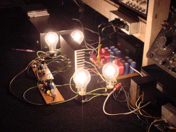
construction, and that is how I have built several of these. Keep the wire lengths down around 6 inches or less and terminate all the grounds of Figure 5 at one point. If you build an unregulated supply for V+ and use a large electrolytic capacitor for its filter, then connect all of its ground connections at a separate single point. Connect these two ground points, The main supply and Figure 5, with a fat piece of wire. In this manner, the large current pulses going through the main electrolytic of the unregulated supply will not pollute the nice clean signal grounding point of Fig. 5. Later we will look at a sample unregulated supply.
Spotlight on Performance
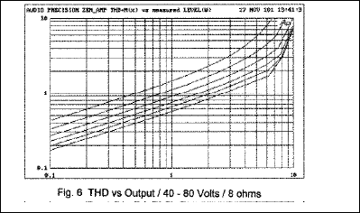
Figure 6 shows the total harmonic distortion plus noise of the circuit of Fig. 5 versus output power into 8 ohms. The gain has been set at 10 dB, and the supply voltage has been varied from 40 to 80 volts. The lowest distortion accompanies the highest voltage, and this effect is due to the higher bias current going through the MOSFET. In general, the higher the bias current, the lower the distortion.
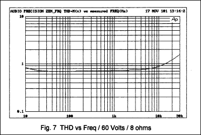
Figure 7 shows this same amplifier with distortion versus frequency and the supply voltage fixed at 60 volts and an output level of 1 watt. This is quite good, as the distortion rises only slightly at 10 Hz and 20 Khz.
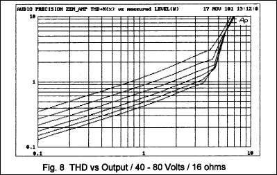
Figure 8 shows the distortion as in Figure 6, but with a 16 ohm load. For a given output voltage (not wattage), we see that the distortion is nearly half. This is what we expect, as the dominant source of distortion is variation in current through the gain device.
Keep in mind that the Zen amp is a polarity inverting circuit. To keep
IRFP240 (top curve at 1 KHz), the IRFP040 (bottom curve) and matched parallel IRF240's (middle). Here we see that the IRFP040 is clearly the best choice, but we note that its distortion at the highest frequencies is about the same as the IRFP240. The source of distortion rise at high frequencies is the non-linearity in the input capacitance of the MOSFETS. If you parallel devices you will see the greater capacitance and the kind of effect illustrated in this curve, where the distortion is lower at lower frequencies, but higher at the top end.
This phenomenon tells us something about our choices of MOSFETs for this circuit. Comparing devices such as IRF230, 240, and 250, we see current ratings of 9, 18, and 30 amps. We also see capacitances of 600 pF, 1300 pF, and 2600 pF respectively. These figures are proportional to chip size, and we see from actual testing that we get similar performance from 2 IRF230's in parallel as compared to a single IRF240. Also. the IRFP250 behaves similarly to a pair of IRF240's.
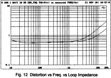
In general, the bigger the chip, the better performance through the low and mid frequencies, but the higher distortion at the top end. This distortion is affected by the impedance of the network driving the gate of the device, and as this impedance goes up, so does the distortion at high frequencies.
Fig 12 illustrates this with comparative performance with distortion curves for a 2.5Kohm potentiometer value vs 5 Kohm value. The curves diverge a bit above 2 KHz, and at 20 KHz the distortion of the 5 Kohm pot is nearly twice.
Lightly Balanced
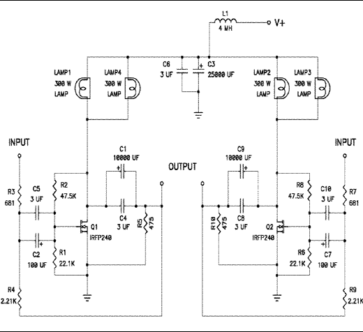
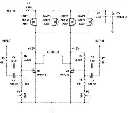
You can operate the Zen amp in balanced mode if you have a balanced source, such as the output of the Bride of the Son of Zen (Audio Electronics 5/97). Figure 15 shows how this can be accomplished using to identical channels sharing a common supply. (If you are employing both separate Ch 1 and Ch2 of Figure 22, you need to attach the V+ and Ground connections of the two channels to each other.) In the stereo amplifiers I built, I put an XLR connector on the amplifier and wired the ground to pin 1, and the two inputs to pin 2(+) and 3(-) for use as a balanced input.
The loudspeaker is attached across the outputs. The advantages to this circuit are mainly cancellation of 2nd harmonic distortion and common rejection of any noise from the supply.
By the way, you will probably not need the turn-on thump circuit with balanced operation, but it won't hurt.
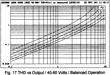
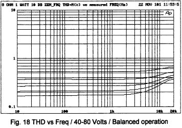
Another potential benefit to balanced operation is the elimination of the output capacitors, as illustrated by the circuit of Figure 16. While the 15 volts or so appears at the loudspeaker, it is the same on both sides, and thus is 0 from the speaker's standpoint. It is important to have these two DC voltages equal, and if you match Q1 and Q2 well, the offset is about 30 mV or so. Lacking that fine degree of matching, I have provided potentiometers P1 and P2 which allow fine adjustment of the DC value. The performance of this circuit with a single pair of 300 watt bulbs is shown in Figures 17 and 18. Here we can see the fairly dramatic distortion reduction due to cancellation of 2nd harmonic.
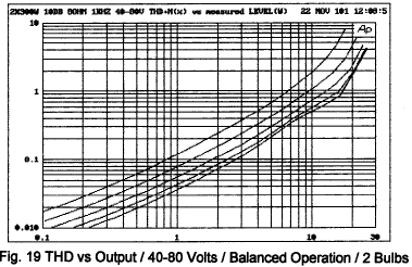
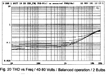
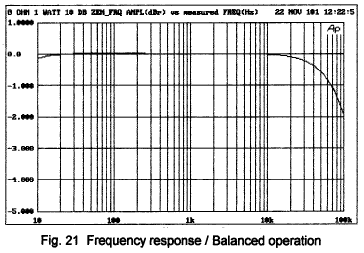
Put two 300 watt bulbs on each side, and the improvement becomes more pronounced, as seen in Figures 19 and 20. With an 80 volt rail the amplifier now makes it up to 20 watts. Figure 21 shows the frequency response of this circuit, which is down 2 dB at 100 KHz.
I built some with three 300 watt bulbs in parallel also: BWAAAHAHAHAA!
Energy Converter For Photonic Emission Bias Bulbs
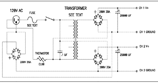
Figure 22 shows an example of the unregulated supply. This is a standard sort of circuit, and the caveats and comments from the other Zen amps apply here. Several of the choices in this circuit will depend on the supply voltage and the number and type of light bulbs you will be using.
The fuse should be a slow blow type set as low as possible, that is to say one value higher than a value which pops often. Start at 2 amps and go up. The on/off switch should be a heavy duty type, rated at 15 amps or better for reliable operation. I have placed a Thermistor in the circuit (Digikey KC006L-ND) which reduces inrush current. The .1 uF capacitor across the line must be line voltage rated, and this one is
Digikey P4603-ND. Both the Thermistor and line capacitor are optional, as is the power switch. The fuse is not optional.
The bridge rectifiers are simply generic high current types. I recommend 200 V 35 amp types, but I know that a certain number of you are going to run out and get exotic Schottky or Ultra-High-Speed-Recovery or Ultra-Soft-Recovery types. Feel free to do so, and consider some nice RC snubbers across the pins while you're at it. You will need to heat sink these bridges, by the way. I simply mounted mine on the same sink as the output transistors.
The power supply capacitors are whatever big cans you want to get that are rated at the voltages you will be using. Big is good, but 1 Farad is too good.
You will notice in Figure 22 that I have shown a supply for two channel operation which isolates the secondary supplies from each other. This is a nice touch, but not essential, and if you are planning on operating the two channels balanced, you will need to connect the V+ and Ground connections together at the main capacitors.
As shown, the two supplies are ground isolated, which helps eliminate any ground loops. A connection to earth ground at the wall outlet is provided for safety and this connection goes through a power rectifier bridge. This bridge will conduct at voltages above .6 volts, providing shock protection while raising a small voltage barrier to noise.
The transformer is a more tricky choice. Many of the commercially available stock devices from Avel or Plitron or Toroid correspond to this configuration, but we must select the voltage and power rating. The voltage is easy. Figure out what DC voltage you want for the supply rail, and select a secondary winding which is AC rated at 75-80 percent of that value.
For figuring out the VA rating, use Figure 3 to determine the current drawn by a single bulb for the DC voltage you have chosen (interpolate for a 200 watt bulb). Now multiply this current by the voltage and then by the total number of light bulbs and then by 2. This is the VA rating of the transformer. The factor of 2 times the actual power draw of the circuit covers the "power factor" of the AC to DC conversion and allows a little more for margin. You are encouraged to consider this as a minimum figure.
Let's take an example. We will be using a 60 volt supply with two channels having two 300 watt bulbs each. At 60 volts the 300 watt bulb draws 1.5 amps:
VA rating = 1.5 amps * 60 volts * 4 bulbs * 2
VA rating = 720 watts. Minimum.
If this is too high, use two transformers, one for each bridge.
As always, remember that you are dealing with potentially lethal voltages. If you don't know what you are doing and are unwilling to take personal responsibility for the results, get some technically competent help.
You are welcome to consider using batteries to power this circuit. This can be accomplished by stacking them to get the appropriate voltage. If you take this approach, you can scrap Figure 22 altogether, and also you can eliminate the inductor L1 of the main circuit. Use whatever capacitor to ground for filtering that you like, but I recommend at least the 3 uF film cap.
Conclusion: Some Lucid Observations
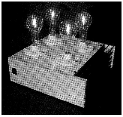
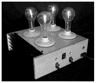
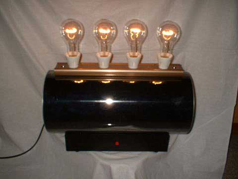
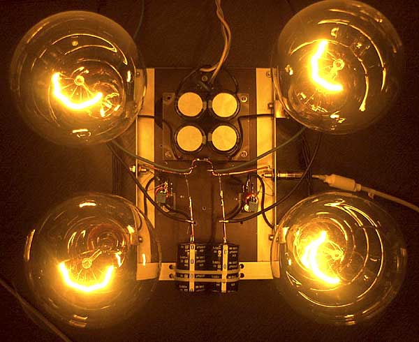
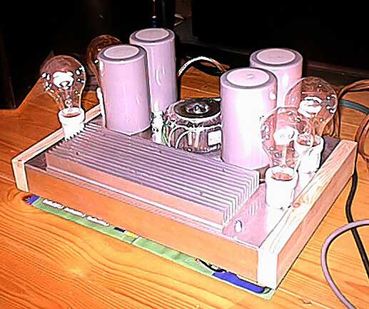
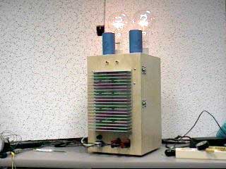
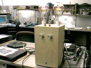
Figure 23 and 24 are photos of the actual amplifier. I made the chassis out of Baltic Birch plywood and finished it with a couple coats of lacquer.
This amp sounds pretty much like the earlier Zen amp. Over the years numerous challengers have opined that their favorite amplifier, (fill in the blank), sounds much better. Probably does.
As I explained first time around, this is an exploration into simplicity, and I make no claim that the Zens are the best sounding amplifiers you can make. They do sound pretty good though, and they are a lot of fun.
If you still need an argument, I'll tell you that Roger Corman and Stanley Kubrick are the greatest film auteurs of the twentieth century…
Special Thanks to Desmond Harrington for layout and production, and Karen Douglass for the photos.
12/1/2001 Nelson Pass / Foresthill California / nelson@passlabs.com
Copyright 2001 Nelson Pass
Less...


