Miscellaneous Projects
My High-Power 130W Amplifier-X. Just after finishing my A4 the diyaudio.com world started buzzing about the new AX schematics. After some time the dust seemed to settle about each and every resistor and cap in the schematics and the group buy of the beautiful finished AX PCB's showed up. I had to get 4 of these!
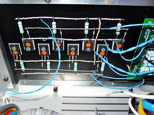
To check the PCB's, the schematics, and to see how this new amp behaves I have build the default 25W version, just like the standard schematics. After finishing one channel I started thinking about a high-power version. So the reading begun. Hundreds and hundreds of postings were read. I wanted to understand how to upscale the schematics. I had to re-calculate some of values of the resistors. For this I found an excel sheet (thanks to wuffwaff) on diyaudio which was a great start. I extended it with all the necessary formula's and graphs to see the effects of voltages, bias and wattages. I settled for 25V-0-25V and 6.7A of bias per channel. Output power will be about 130W at 8 ohm and 90W at 4 ohm! I enclosed the excel sheet with the parameters I used to build my AX . The amount of heat dissipated is about 400W per channel. For this amount of power I have used 16x IRFP240 per channel. So there are 4x IRFP240 connected parallel. I used point to 2 point with silvered OFC wire to connect all IRFP240's together.
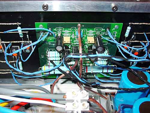
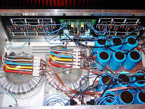
It was a bit of a puzzle how to connect all the IRFP240's the smartest way externally to the PCB's as the PCB's were designed for 4x IRF240 instead of 16! Look at one of the pictures for an idea. I used Kimber 8TC cable for all other connections.
Changes to Grey's circuit (hifizen PCB):
22-0-22 1000VA transformer (gives 25-0-25 DC)
BIAS resistors = 0.56 ohm
R17 = 6k8 (6mA running through zener diode).
R14, R31 = 1k5
R15, R32 = 1k5
R34, R12 = 1K pot meter which I adjusted by hand (ACS gain)
C2, C4 = 10pF silver mica
Some of the parts used:
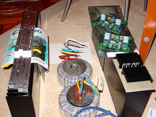
2x Amplimo 1000VA 25-0-25
12x BC components model 154 22000uf 63V
8x IR MBR2045 diodes
Lots of InterTechnic MOX4 and MOX10 resistors
0.1% 0.5W BC metal film throughout
8TC Kimber cable
QED silvered OFC
8x Blackgate FK 220uf 25V
4x Silvered Mica caps 10pF
4x Seifert heat sinks KL271-200mm
32x IR IRFP240
6x IR IRF9610
Conrad front switch vandal proof
Conrad impulse relays
My power supply uses: 6x BC components model 154 22000uf 63V elco's per channel which are in CRCRC filter where each R = 2 times 10W 0.22 (=0.11) parallel. This gives me a power supply ripple of about 0.5V top-to-top on full 6.7A of bias load. For the rectifier I used 4x IR MBR2045 diodes per channel. I hear NO HUM whatsoever... When you connect to amp to something or short the input of the amp it is dead silent, no hiss, no hum, nothing on my 92db/W/m loudspeakers!
I am using the 'ground' resistors to control the absolute DC. I used 2x 47ohm 10W parallel resistors to ground for each side of the channel. You can look on one of the pictures how I positioned them on the PCB.
I have adjusted the active current source by running 9V RMS of 1K sine through the amp. To find the right value for the R12 and R34 resistor I first used a pot meter which I later replaced with a normal resistor with the right value when all was stable and ok.
I changed from 5pF to 10pF per side for C2 and C4. With 5pF I had ringing (overshoot) on the edges of a square wave at 10 kHz.
The AX is very sensitive to the matching of the IRF9610 pair and the IRF240's of the negative sides of the amp. I had to re-match 3 times to get a good pair of IRF9610 and I had to swap 6 of the 16 negative IRF240's around to get a good (low) and stable DC offset. To get two pairs of IRF9610 I had to go through 40x IRF9610's. I measured VGS over 5 minute's time and tried to find two IRF9610 which tracked (measured) the same of this period.
This took some time! Perhaps the new way of matching which Nelson recently has put on http://www.passdiy.com will help you out!
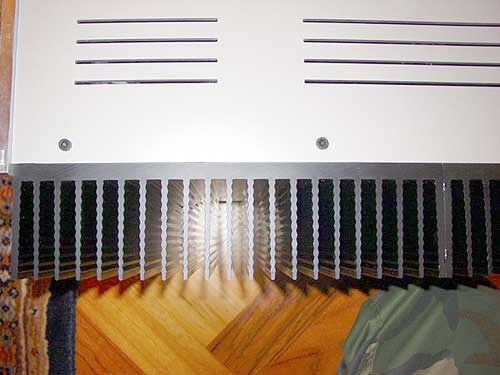
My case is constructed with 12mm x 12mm aluminium bars in which I have drilled 4.2mm holes and made 5mm thread. With these bars I connected the Seifert heat sinks and the panels (ordered at http://www.schaeffer-apparatebau.de/) together to get a very heavy case. The amp dissipates about 800W of heat and runs in my room at about 55-58 degrees Celsius. Of course two blue leds to top it off!
It will deliver:
Watts Ohm
132W 8.00
151W 7.00
134W 6.00
112W 5.00
89W 4.00
67W 3.00
44W 2.00
Both channels behave great for some months now and have absolutely no problem driving my B&W Nautilus 802's. Connected with a balanced cable from an AP I have a stable 30mV of DC offset on both channels. The absolute DC offset is around -100mV to 100mV, the temperature of the room and the heat sinks are in direct relation to the absolute DC offset. The amp sounds delicious, velvet highs with great precision and a huge soundstage. The bass is much better than my old A4. Tight and deep. All in all it is a more complete amp in every way in comparison to my A4.
Thanks for Nelson and all the others at http://www.diyaudio.com !!!
Edwin Dorré
The Netherlands
P.S. Sorry for the bad English, English is not my


